For electrical wholesalers, project contractors, and technical buyers, a BS wall switch or socket is judged not only by appearance but by how reliably it can be installed on site. A clean installation workflow reduces labor time, lowers rework risk, and helps projects move from rough-in to handover with fewer callbacks.
This page is designed as a practical BS standard wall switch and socket installation guide for professional use. It focuses on planning, product fit, terminal access, mounting stability, and post-installation checks rather than DIY instruction. If you need product-level compliance checks before installation, review our BS1363 wall socket specification guide. If you need wider standards context, use our standard electrical outlet guide.
A professional installation workflow starts before any conductor is terminated. Product fit, back box compatibility, terminal access, and final testing all affect whether a BS accessory performs well after commissioning. That is why installation quality should be treated as part of product selection, not just site execution.
Phase 1: Pre-Installation Planning & Specification
A flawless installation begins long before a single wire is connected.
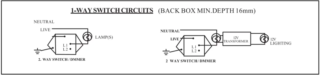
Confirming Back Box Compatibility: Ensure the specified back boxes have the correct depth to accommodate the chosen device, especially for modules with deeper profiles such as USB chargers or dimmers. Before the box schedule is locked, project buyers should also confirm whether each BS1363 socket position needs a single or double format; our single vs double BS1363 socket selection guide explains how to make that decision from BOQ, room function, and back box planning. LIBAIK series built for BS projects are designed for standard BS back boxes, but box condition and available working space should still be checked before site installation.
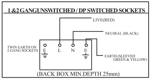
Verifying Circuit Load and Wire Gauge: Match the device rating, such as 13A for sockets or 10A and 16A for switches, with the circuit protective device and conductor size used on site. For BS-compliant socket installations, ring final circuits are common in many projects, but the actual circuit arrangement should always be checked against site design and local practice.
Choosing the Right Series for the Job
- For speed and efficiency in large projects: Large, accessible terminals help electricians terminate conductors more quickly and with better control. In the LIBAIK range, the L11 is a representative example.
- For a premium, seamless finish: A two-part design allows the mounting grid and back-end wiring to be completed before the final decorative faceplate is installed, reducing finish damage during construction. In the LIBAIK range, the V7 shows this approach clearly.
Pre-Installation Checklist
- confirm the accessory type, rating, and switched or unswitched configuration
- check back box depth, mounting points, and enclosure condition
- verify conductor size and circuit arrangement before bringing the device to site
- confirm that decorative and functional expectations match the selected series
- review product-level BS compliance details before installation begins
Phase 2: The Installation Process - Where Quality Engineering Matters
This is where the design of the wiring device itself plays a critical role.
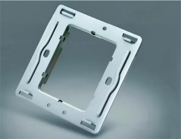
1. Secure Mounting Frame Installation
The foundation of a stable installation is a mounting frame that resists warping and remains level against the wall. Reinforced steel frames help the device stay flat, even where wall surfaces are not perfectly even. In the LIBAIK range, the V6 and V12 series are typical examples of this design approach.
2. Efficient and Secure Wire Termination
- Terminal design: High-quality terminals, such as nickel-plated alloy terminal structures used in higher-grade BS accessories, improve corrosion resistance and provide stronger clamping force on conductors.
- Wiring space: A chassis with more usable space reduces conductor strain and makes it easier to terminate thicker wires cleanly and quickly. This matters more on real projects than decorative styling does.
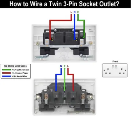
- BS 1363 wiring standard: For projects using BS color identification, Brown is Live (L), Blue is Neutral (N), and Green/Yellow is Earth (E). Site work should always follow local code and qualified electrician procedure.
3. Device Mounting and Faceplate Attachment
- The device should be fastened securely to the back box without twisting the mechanism or forcing conductors behind the plate.
- For screwless models: the faceplate should click into place cleanly, with no gaps or loose edges. This final step saves time on site compared with traditional screwed plates and helps protect the decorative surface until late in the installation sequence.
What Incorrect Installation Often Leads To in Real Use
This is the part many generic installation articles skip. Poor installation does not always fail immediately. In many cases the accessory appears normal at handover and only starts showing symptoms after repeated switching, plug insertion, or load use. That is why contractors should think in terms of failure modes, not only completion steps.
| Installation fault | What may happen in service | Why it happens |
|---|---|---|
| Terminal screw not tightened correctly | The switch or socket may produce a buzzing or crackling sound under load, show intermittent operation, or develop local overheating. | Weak clamping force increases contact resistance. Resistance under load creates heat and can lead to arcing at the terminal. |
| Insulation caught under the terminal clamp | The accessory may work at first but later overheat, discolor, or fail after repeated use. | The conductor is not making full metal-to-metal contact, so current flows through a poor connection area with elevated heat buildup. |
| Exposed copper left outside the terminal zone | The installation may fail inspection, create shorting risk, or expose conductive parts to accidental contact inside the box. | Termination length was not controlled properly, leaving bare conductor beyond the intended clamping area. |
| Back box too shallow or conductor space too tight | The plate may not sit flat, conductors may be crushed behind the mechanism, and long-term reliability may drop. | Mechanical stress is transferred into the terminated conductors when the device is forced into position. |
| Poor polarity or earthing connection | The circuit may fail testing, behave unsafely in service, or create serious acceptance and maintenance problems later. | Core safety checks were skipped or wiring identification was not verified before energization. |
Phase 3: Post-Installation Testing & Commissioning
A professional installation is not complete without rigorous testing.
- Mechanical checks: Confirm that switches have a positive action and that sockets hold a plug firmly, with no visible looseness or plate misalignment.
- Electrical testing by a qualified professional: This typically includes continuity checks, polarity checks, and insulation resistance testing to confirm that the installation is safe and aligned with project requirements.
Field symptoms after energization should never be ignored. Buzzing, crackling, unusual warmth, visible discoloration around terminals, unstable switch action, or repeated plug looseness are not minor finish issues. They often indicate poor contact pressure, stressed conductors, incorrect termination, or an installation condition that should be reopened and corrected by a qualified professional before continued service.
Specifying and installing wall switches and sockets is a critical process in which product design directly affects project efficiency, safety, and final quality. Reinforced steel frames, spacious terminal access, and two-part decorative structures are not cosmetic details; they influence installation speed, mounting accuracy, and the likelihood of rework after energization.
For broader cross-market outlet context after installation review, continue to electrical outlet types around the world. This helps project teams compare BS accessories with other national outlet systems when specifications or market requirements differ.
Choose a partner who understands the full project lifecycle. Explore our BS standard wiring accessory series or contact our project team to discuss which LIBAIK range is the best fit for your next installation project.