Why Do Wall Switches Overheat Under Load? The Role of Conductor Material in Long-Term Electrical Reliability
Wall switch overheating is often linked to internal conductor material and structural design rather than external appearance. This article explains how electrical conductivity (IACS standard), contact resistance, and temperature rise behavior influence long-term reliability in commercial and high-load applications. It compares pure copper, brass alloys, and lower-conductivity alternatives from an engineering perspective.
Why Do Wall Switches Overheat Under Load?
The Role of Conductor Material in Long-Term Electrical Reliability
Overheating in wall switches and sockets is one of the most common field complaints in commercial and residential projects.
Contractors report faceplate discoloration.
Distributors receive feedback about burning smells.
Facility managers encounter unstable connections after only a few years of operation.
In many cases, the external design looks perfectly fine. Certification marks are present. Installation was done correctly.
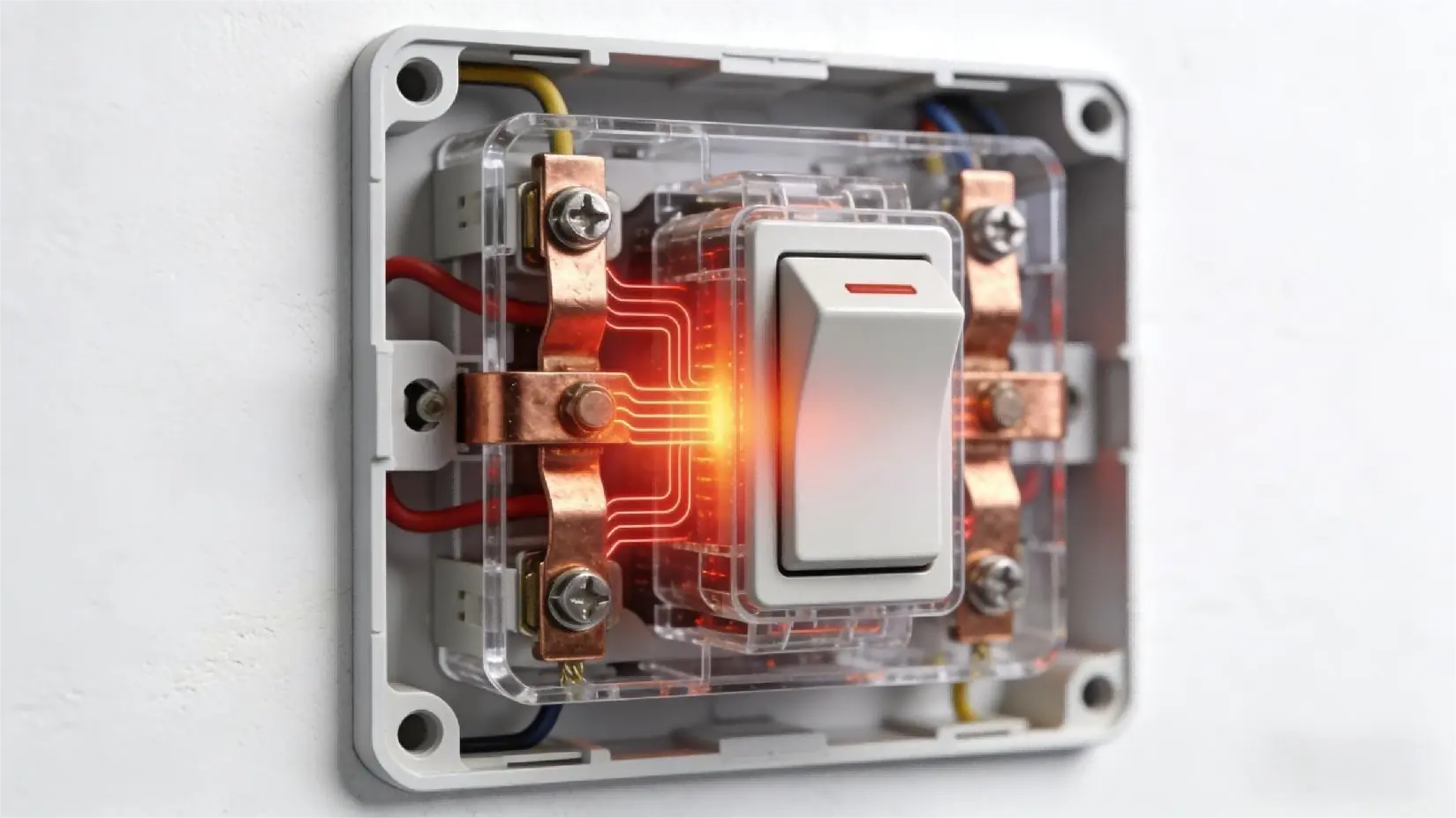
The real cause is often hidden inside the product — the internal conductor material and structure.
Understanding why wall switches overheat under load requires looking at electrical conductivity, contact resistance, and long-term thermal behavior — not just surface appearance.
Why Do Wall Switches Overheat in Commercial Projects?
When a switch or socket carries current, electrical resistance converts part of that energy into heat. The relationship is defined by the basic electrical formula: P = I²R
Where:
P = heat (power loss)
I = current
R = resistance
Even small increases in resistance can generate significant additional heat under high current.
Under light household use, this heat may be negligible.
Under commercial conditions — high-wattage appliances, continuous load, or dense installations — the temperature rise becomes more significant.
Several factors contribute to overheating:
- Low conductivity conductor material
- Poor contact surface design
- Multi-part internal assemblies
- Long-term oxidation increasing contact resistance
In high-temperature regions such as the Middle East, ambient wall temperatures can already exceed 50–60°C in summer. Any additional internal heat accumulation accelerates material fatigue and insulation stress.
Overheating is rarely a single-event failure. It is usually a slow thermal accumulation process.
How Conductor Material Affects Heat Generation
A common B2B question is:
How does conductor material influence switch overheating?
The answer lies in electrical conductivity. According to the International Annealed Copper Standard (IACS):
- Annealed pure copper is defined as 100% IACS conductivity, approximately 58 MS/m
(Referenced in ASTM B193 and IEC 60228)
Typical brass alloys — depending on zinc content — generally range between 20–40% IACS conductivity.
Pure copper has significantly higher conductivity than brass alloys or ferroalloy-based substitutes. Higher conductivity means:
- Lower electrical resistance
- Less energy converted into heat
- More stable current flow
When lower-conductivity materials are used, resistance increases. Even small differences in resistance can create measurable temperature rise under sustained load.
Over time, repeated heating and cooling cycles increase micro-oxidation at contact points, further raising resistance — creating a compounding effect.
This is why conductor material selection is directly linked to long-term reliability.
Brass vs Copper in Electrical Switch Parts
Brass is commonly used in electrical parts because it is:
- Higher mechanical hardness
- Easier to machine
- Lower in raw material cost
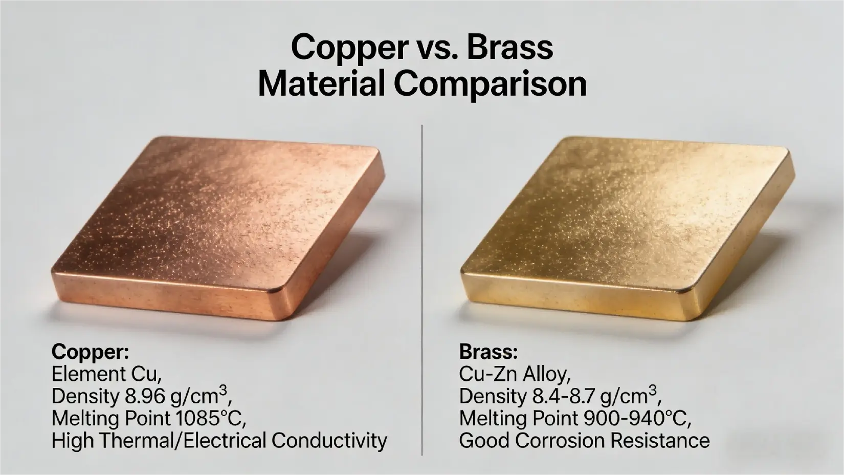
However, brass is a copper–zinc alloy, and its electrical conductivity is significantly lower than pure copper.
Under normal load conditions, brass may pass certification testing.
Under high or continuous load, it tends to generate more heat at contact points.
In lower-cost designs, some manufacturers go further by using ferroalloy components with surface plating to simulate copper appearance. These materials reduce cost but introduce even higher resistance and faster thermal buildup.
From an engineering standpoint, the difference is not cosmetic — it is thermal and electrical.
| Property | Pure Copper | Brass |
| Conductivity (IACS) | 100% | 20–40% |
| Resistance | Low | Higher |
| Heat Generation | Lower | Higher under load |
| Long-Term Stability | High | Moderate |
The Hidden Risk: Multi-Part Conductors and Contact Resistance
Material is only part of the equation.
Structure matters equally.
Many lower-cost switches use multi-part internal conductor assemblies:
1. Riveted joints
2. Welded connectors
3. Screw-fastened current paths
4. Wired bridging elements
Each interface introduces an additional contact resistance point.
Under repeated thermal cycling, these interfaces may loosen microscopically, increasing resistance and localized heating.
A one-piece solid copper conductor reduces:
(1) Interface resistance
(2) Structural fatigue
(3) Long-term instability
Fewer connection points mean fewer opportunities for resistance buildup.

IEC Temperature Rise Standards — and Their Limits
Many buyers assume that IEC certification guarantees zero overheating risk.
In reality, IEC temperature rise testing evaluates products under defined laboratory conditions and time frames. These tests verify compliance — they do not simulate ten years of high-load commercial operation.
Key considerations often overlooked:
a. Ambient temperature variation
b. Continuous vs intermittent load
c. High-power appliances
d. Installation density in commercial projects
A product can pass IEC temperature rise limits while still operating close to thermal thresholds in real-world environments.
Conductor material with higher conductivity provides a wider safety margin.
High-Temperature Markets: Why Environment Changes Everything
In regions such as Iraq, Saudi Arabia, and Southeast Asia, high ambient temperature adds stress to every electrical component. This is particularly relevant when evaluating surface materials in hot climates, as discussed in our article on high-temperature switch performance.
When wall temperatures already approach 60°C:
- Insulation aging accelerates
- Contact oxidation increases
- Heat dissipation becomes less efficient
Under these conditions, the difference between pure copper and lower-conductivity materials becomes more pronounced.
What may perform adequately in mild climates may behave differently in high-temperature markets.
How B2B Buyers Can Reduce Overheating Risk in Wall Switches
For B2B buyers sourcing switches for commercial or high-load environments, risk reduction starts with asking the right technical questions:
1.What is the conductor material specification?
2.Is the internal conductor one-piece or assembled?
3.What is the conductivity grade of the copper used?
4.How is contact resistance controlled over time?
5.What is the temperature rise margin under rated load?
Selecting high-conductivity pure copper conductors and minimizing internal connection interfaces significantly reduces long-term overheating risk. For sourcing considerations beyond conductor material, refer to our guide on how to choose a reliable switch manufacturer.
This is not about premium positioning — it is about electrical physics.
Conclusion
Wall switch overheating is rarely caused by external design. It is usually the result of cumulative thermal stress driven by material choice and internal structure.
Pure copper conductors provide:
- Lower resistance
- Reduced heat generation
- Greater long-term stability
Brass and ferroalloy alternatives may reduce initial cost, but they operate with narrower thermal margins under sustained load.
✅ FAQ: Wall Switch Overheating and Conductor Material
1. Why do wall switches overheat under load?
Overheating occurs when electrical resistance inside the conductor or contact interface converts current into heat (P = I²R). Lower-conductivity materials increase resistance and heat generation under sustained load.
2. Does IEC certification guarantee no overheating risk?
IEC certification confirms compliance under standardized testing conditions. Real-world performance depends on installation environment, load duration, and design margin. For more details on how manufacturing controls influence long-term performance, see our Manufacturing Process & Quality Control guide.
3. What material is commonly used inside wall switches?
Common materials include pure copper, brass alloys, and in some cases plated or ferrous-based substitutes. Conductivity varies significantly between these materials.
4. What is the best conductor material for commercial-grade wall switches?
For high-load commercial applications, high-conductivity copper offers lower resistance and improved long-term thermal stability. Final selection should align with project load profile and environment.
✅ Technical References
ASTM B193 – Standard Test Method for Resistivity of Electrical Conductor Materials
IEC 60228 – Conductors of Insulated Cables
IEC 60669-1 – Switches for Household and Similar Fixed Electrical Installations
IEC 60884-1 – Plugs and Socket-Outlets for Household and Similar Purposes
International Annealed Copper Standard (IACS)